An LED and a button
Here your program starts to handle things outside it: it turns an LED on, toggles it with a button and sets its brightness. First on Windows, with the GPIO simulator, which acts as a board with an LED and a push button you click with the mouse. Then on your board, with a real LED and button. The program is the same in both places.
Use the project from Your first program or create another one with Home › Project › New. Each program on this page goes in the main file, Code/Tutorial.aru (or your project's), in place of what it has.
Turn an LED on and off
use GPIO

const PIN_LED = 2                    // the LED pin

GPIO.pinmode(PIN_LED, GPIO.OUTPUT)   // an output pin
for (var blink = 1; blink <= 5; blink++)
    GPIO.write(PIN_LED, HIGH)        // on
    pause(500)
    GPIO.write(PIN_LED, LOW)         // off
    pause(500)
end
println("Done")
use GPIObrings in the pin module, GPIO.GPIO.pinmodemakes the pin an output, andGPIO.writesets it high (HIGH: the LED turns on) or low (LOW: it turns off).pause(500)waits half a second.
On Windows, the LED is a card of the simulator:
- Open the simulator with Build › Debug › GPIO Sim.
- Click Add GPIO Pin, type
2in GPIO Number (0-48) and click OK. The pin shows up in the table, free. - Click its Connected to column, choose Red LED and press
Enter. Its card shows up on the right, Red LED · GP2. - Click Run. The LED on the card turns on and off five times, and next to it reads
ON (HIGH)orOFF (LOW). When it ends, the program's console printsDone.
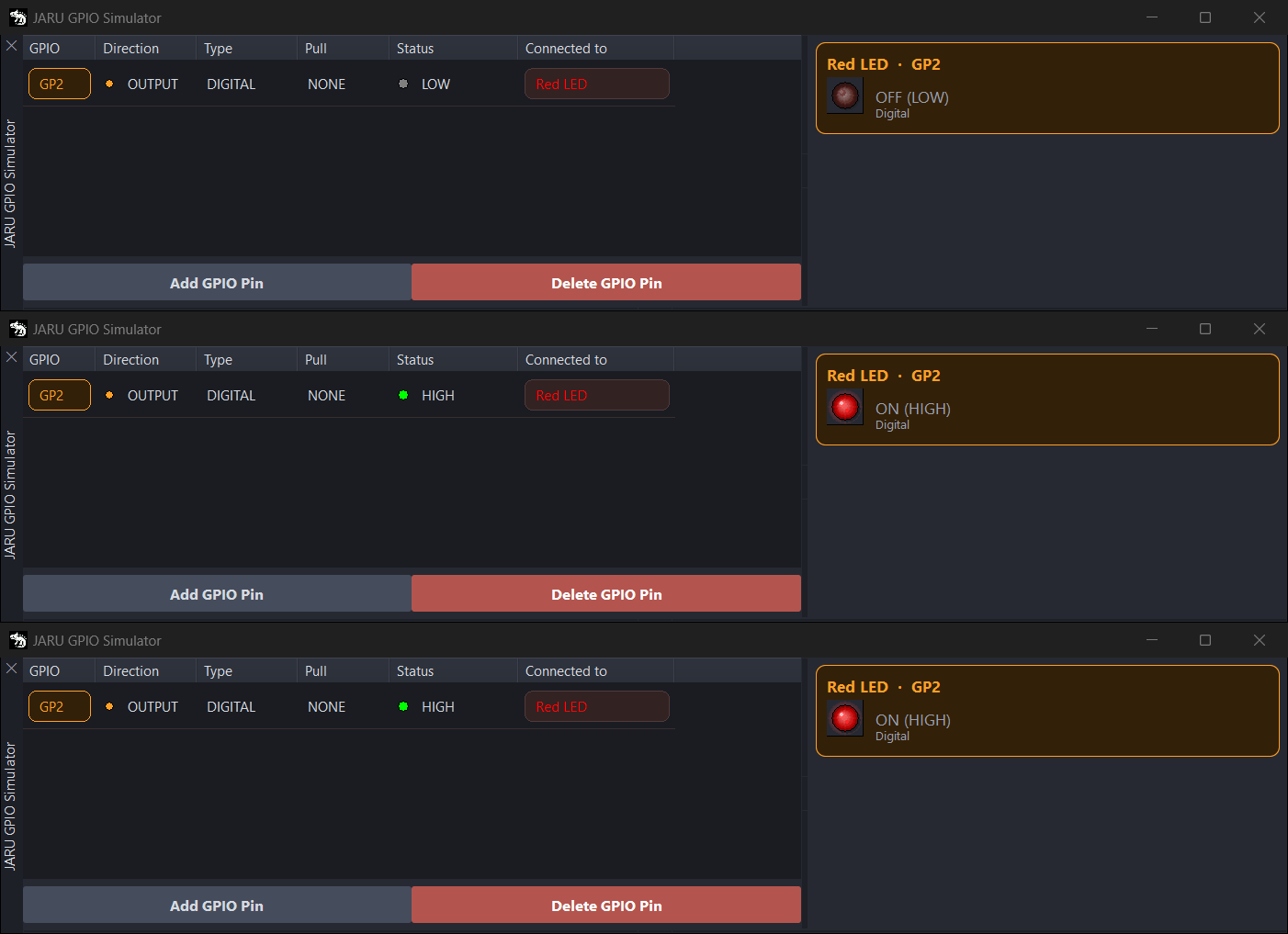
The simulator saves its pins with the project, in Config/jaru_sim.json: next time they will still be there.
Use names such as PIN_LED or PIN_BUTTON, not LED or GPIO: with a variable or a constant named like a module, the program stops when it uses it, without any message, and the compiler gives no warning.
Toggle the LED with a button
Now, a button: each time you press it, the LED toggles.
use GPIO

const PIN_LED = 2
const PIN_BUTTON = 4

GPIO.pinmode(PIN_LED, GPIO.OUTPUT)
GPIO.pinmode(PIN_BUTTON, GPIO.PULLUP)    // released gives HIGH; pressed, LOW

var lit = false
var previous = HIGH
while (true)
    var current = GPIO.read(PIN_BUTTON)
    if (previous == HIGH and current == LOW) then    // just pressed
        lit = not(lit)
        if (lit) then
            GPIO.write(PIN_LED, HIGH)
        else
            GPIO.write(PIN_LED, LOW)
        end
        println("LED on: ", lit)
    end
    previous = current
    pause(20)
end
- With
GPIO.PULLUP, the pin is an input with its pull-up resistor: the button goes between the pin and GND. Released,GPIO.readgivesHIGH; pressed,LOW. - The program does not end:
while (true)reads the button every 20 milliseconds. It compares each reading with the previous one, and only when the button goes from released to pressed does it toggle the LED. That way, holding it down counts only once. - The state of the LED is kept in
lit: the program does not need to read the LED pin.
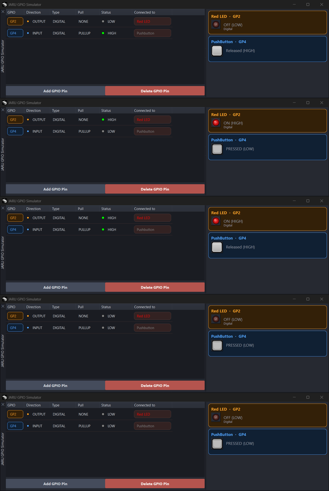
On Windows:
-
In the simulator, add pin
4with Add GPIO Pin and connect it to Pushbutton. -
Click Run and click the button on the Pushbutton · GP4 card. While you hold it down, the card reads
PRESSED (LOW). -
Each click turns the LED on or off, and the console reports it:
LED on: true
LED on: false -
To finish, click Stop.
Brightness, with PWM
An LED does more than turn on and off: with PWM you give it an in-between brightness. Here, each press raises the brightness one step.
use GPIO

const PIN_LED = 2
const PIN_BUTTON = 4

GPIO.resolution(PIN_LED, 8)              // brightness from 0 to 255, on Windows and on the board
GPIO.pinmode(PIN_BUTTON, GPIO.PULLUP)

var brightness = 0
var previous = HIGH
GPIO.awrite(PIN_LED, brightness)
while (true)
    var current = GPIO.read(PIN_BUTTON)
    if (previous == HIGH and current == LOW) then
        brightness = brightness + 85             // 0, 85, 170, 255 and back to 0
        if (brightness > 255) then
            brightness = 0
        end
        GPIO.awrite(PIN_LED, brightness)
        println("Brightness: ", brightness)
    end
    previous = current
    pause(20)
end
GPIO.awriteputs out a signal on the pin that switches on and off very fast. The longer it stays on, the brighter the LED. It does not needpinmode.GPIO.resolution(PIN_LED, 8)sets the scale from 0 to 255. By default it goes from 0 to 255 on Windows and from 0 to 1023 on the board: this way, the same number gives the same brightness on both.
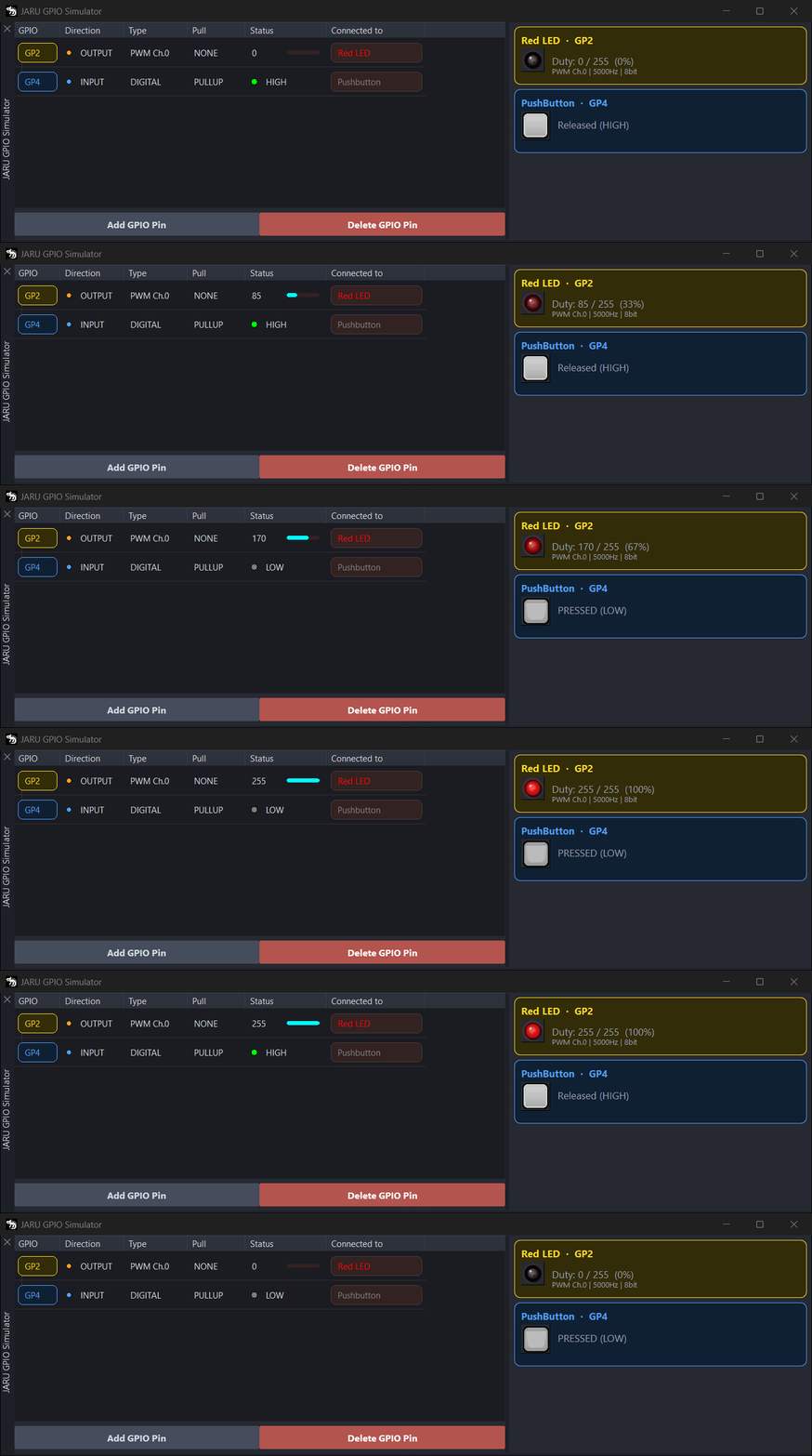
Click Run and click the button a few times: the LED on the card gets brighter with each step, and the card says how much, such as Duty: 170 / 255 (67%). The console prints Brightness: 85, Brightness: 170, Brightness: 255 and Brightness: 0.
On the board
- Choose two free pins on your board: not those of the display, the SD card, the sound or the I2C bus, nor those of the serial console. Which ones they are, in Pins you cannot use for a button. On the ESP32, 34 to 39 are input only and have no internal pull-up: they work neither for the LED nor for this button.
- Wire the LED from the pin to GND, with its resistor in series and the long leg towards the pin, and the button between the other pin and GND.
- Change
PIN_LEDandPIN_BUTTONto your pins. - With your board in Target, click Run and open the serial monitor to see what it prints, as in Your program on a board.
On the board, the blinking LED program starts again when it ends: the VM repeats it. The other two never end; they stay on the board until you send it another program.
Next steps
- A sensor on the network: read an analog value, such as a potentiometer, and send it over the internet with MQTT.
- GPIO module: all the pin functions, the differences between boards and interrupts.
- GPIO simulator: all its cards, from the switch to the strip of color LEDs.